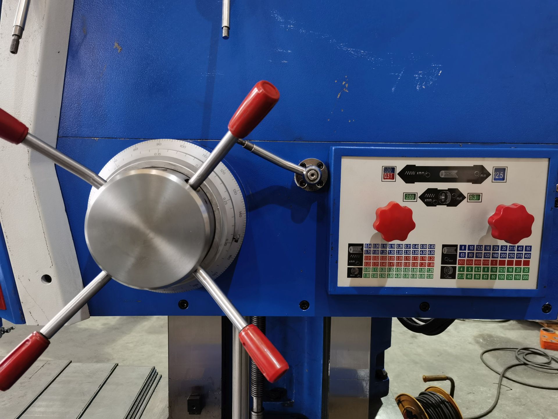
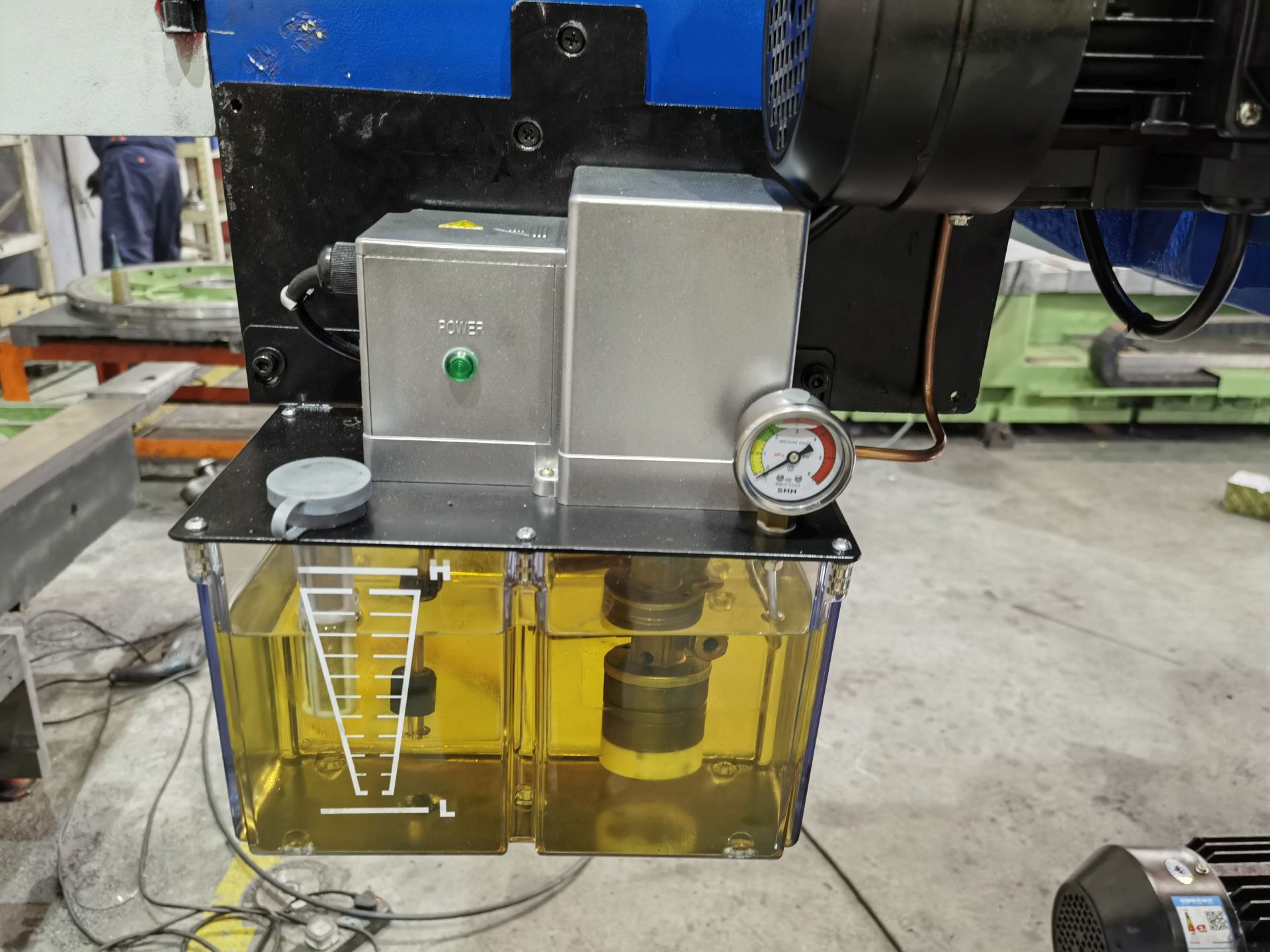
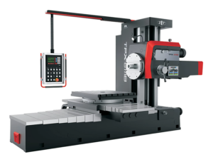
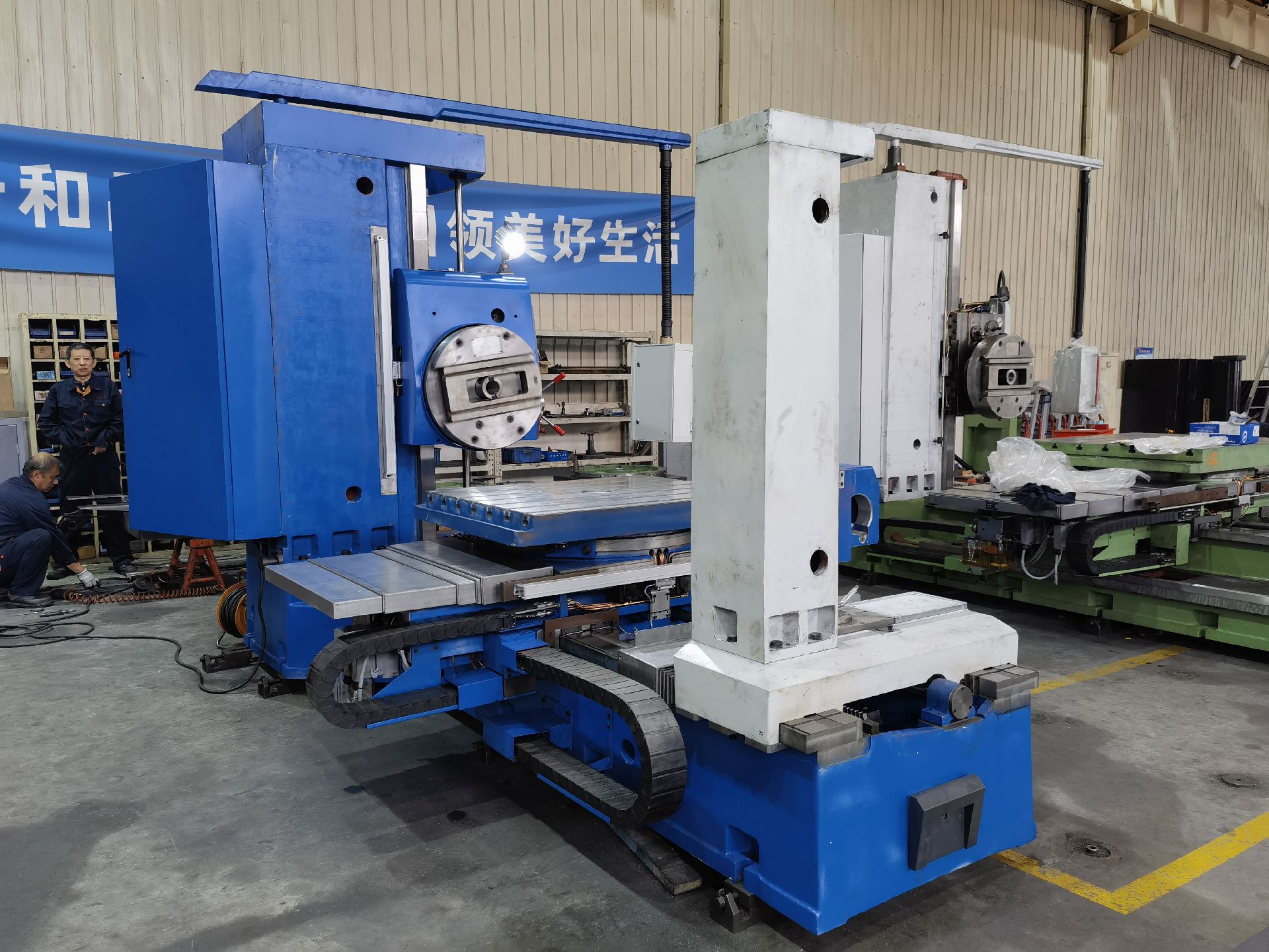
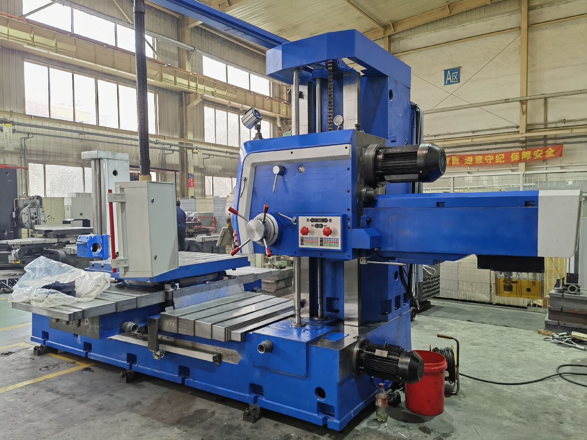
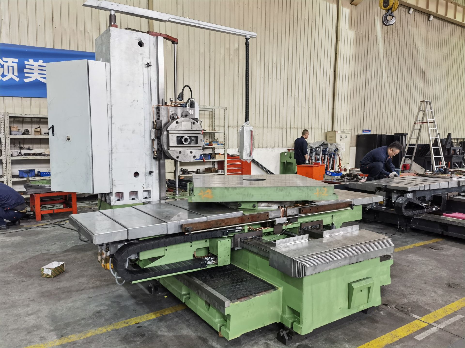
•The spindle speed range 8-1000r/min is realized by frequency conversion motor driving 2 gears.The spindle stepless speed is set and speed value is showed by setting buttons.
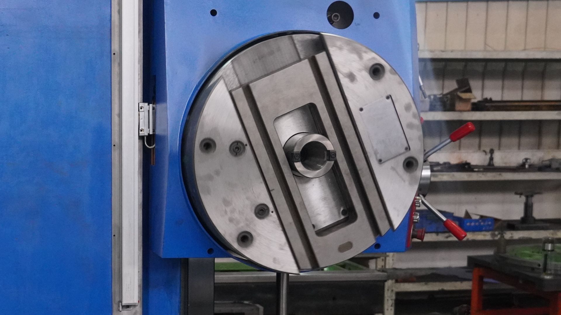
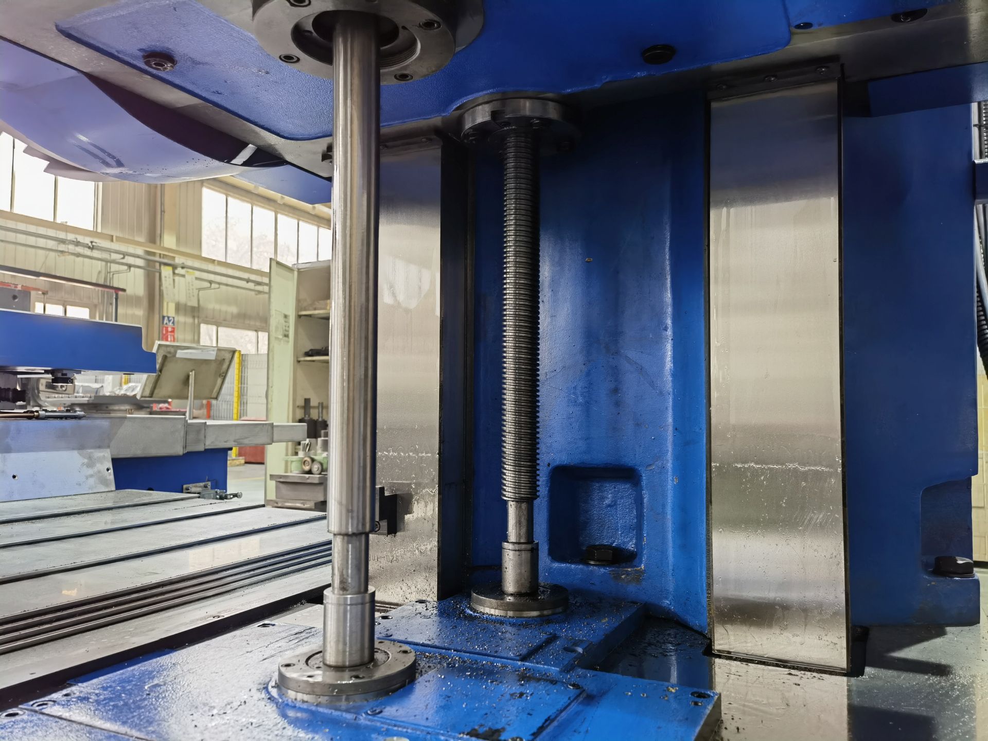
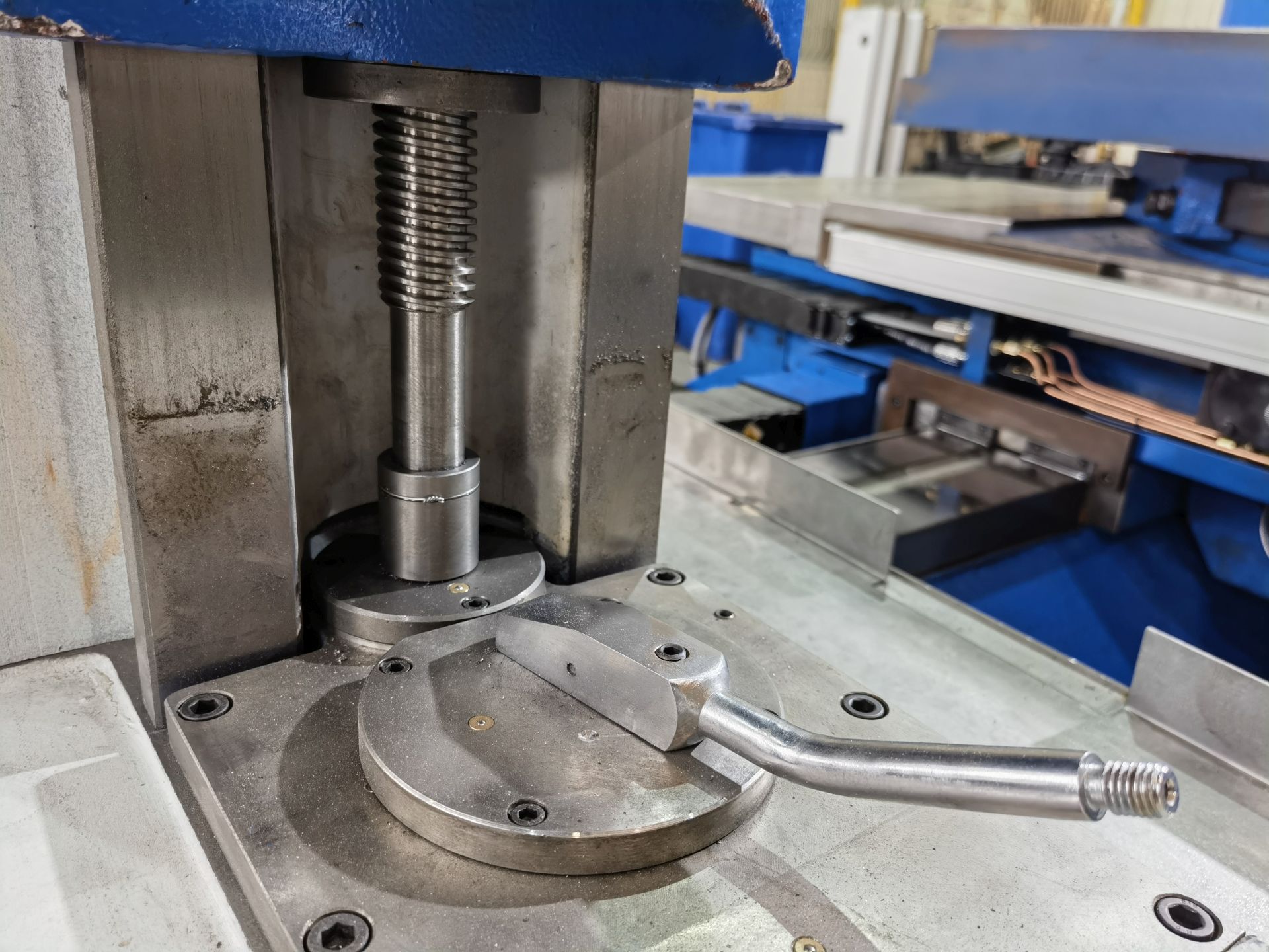
•Spindle taper is 7:24 No.50. This machine is equipped with automatic clamping/umclamping device which shorten auxilary time of clamping/umclamping tool and intensity of labor is reduced. The spindle features with good accuracy for a long time.
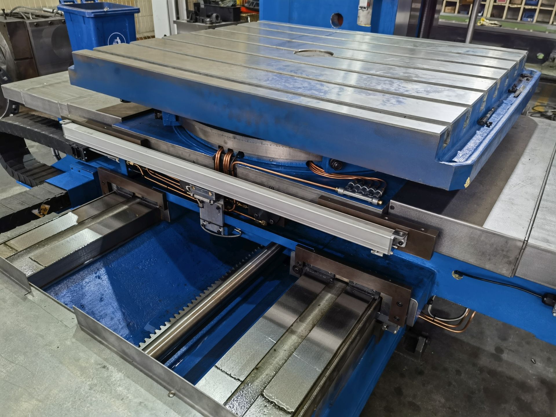
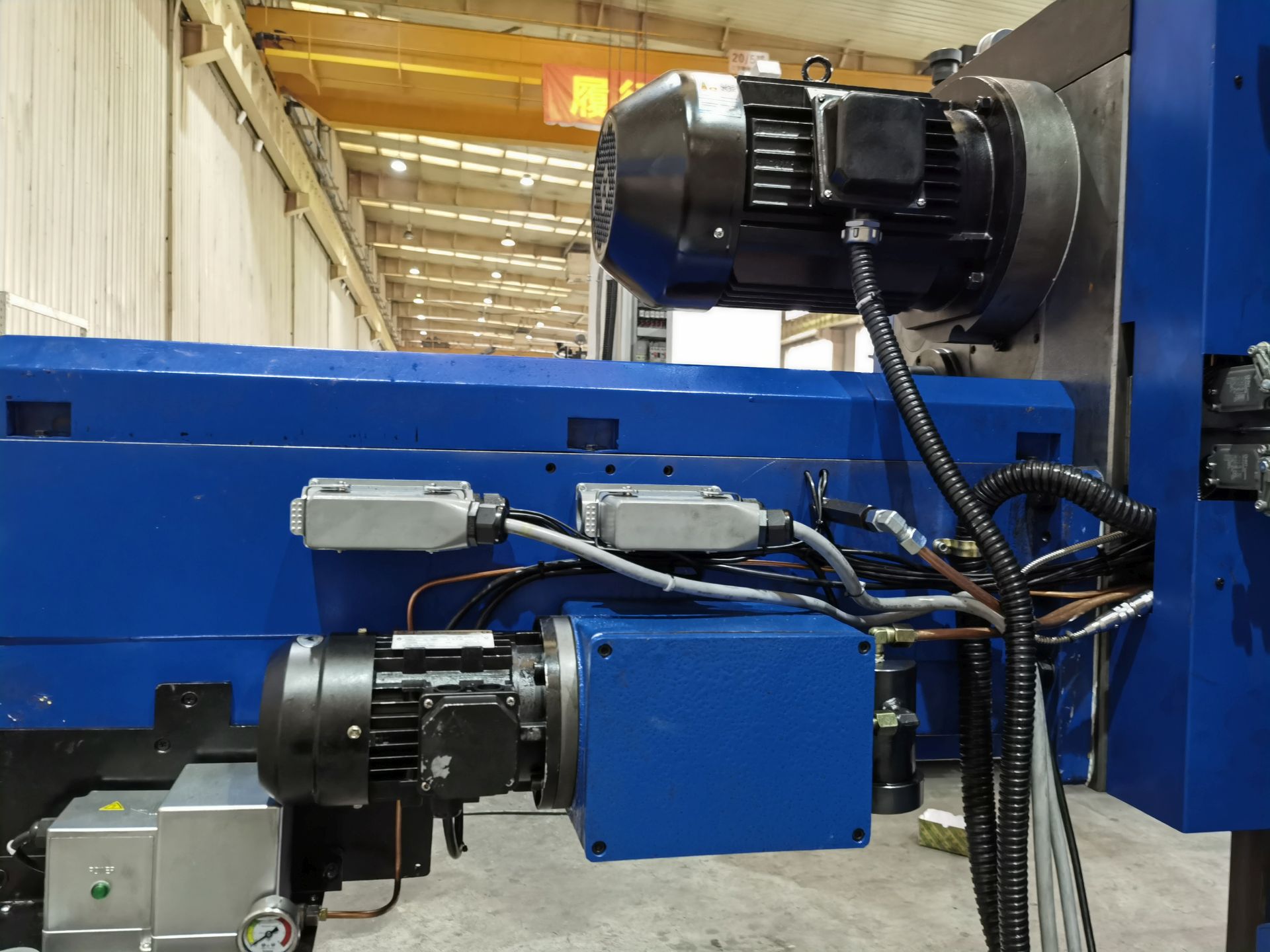
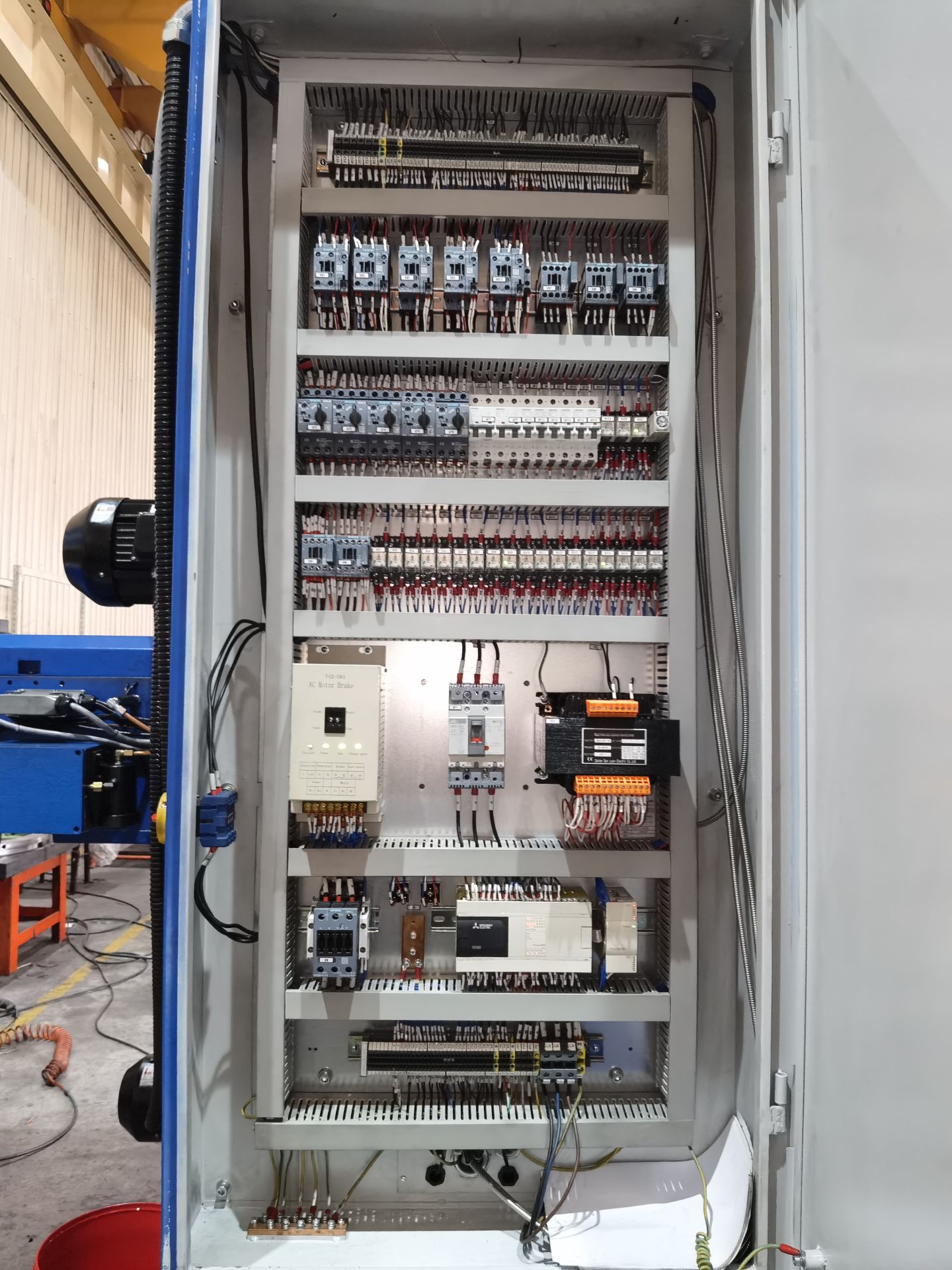
•Each coordinate axis moveing such as spindle, facing head slide, spindle box, longitudinal and cross movement of worktable and worktable rotation are all drove by AC servo motor mounted on bed. The feed stepless is set and the feed speed value is showed by setting buttons through gearbox, eletromagnitic clutch.
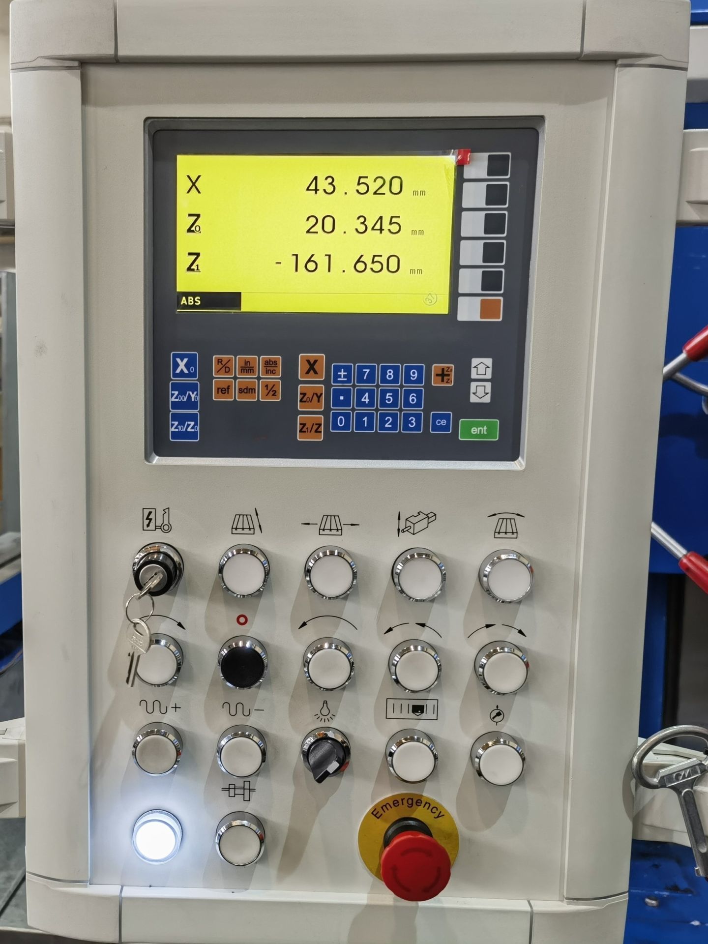
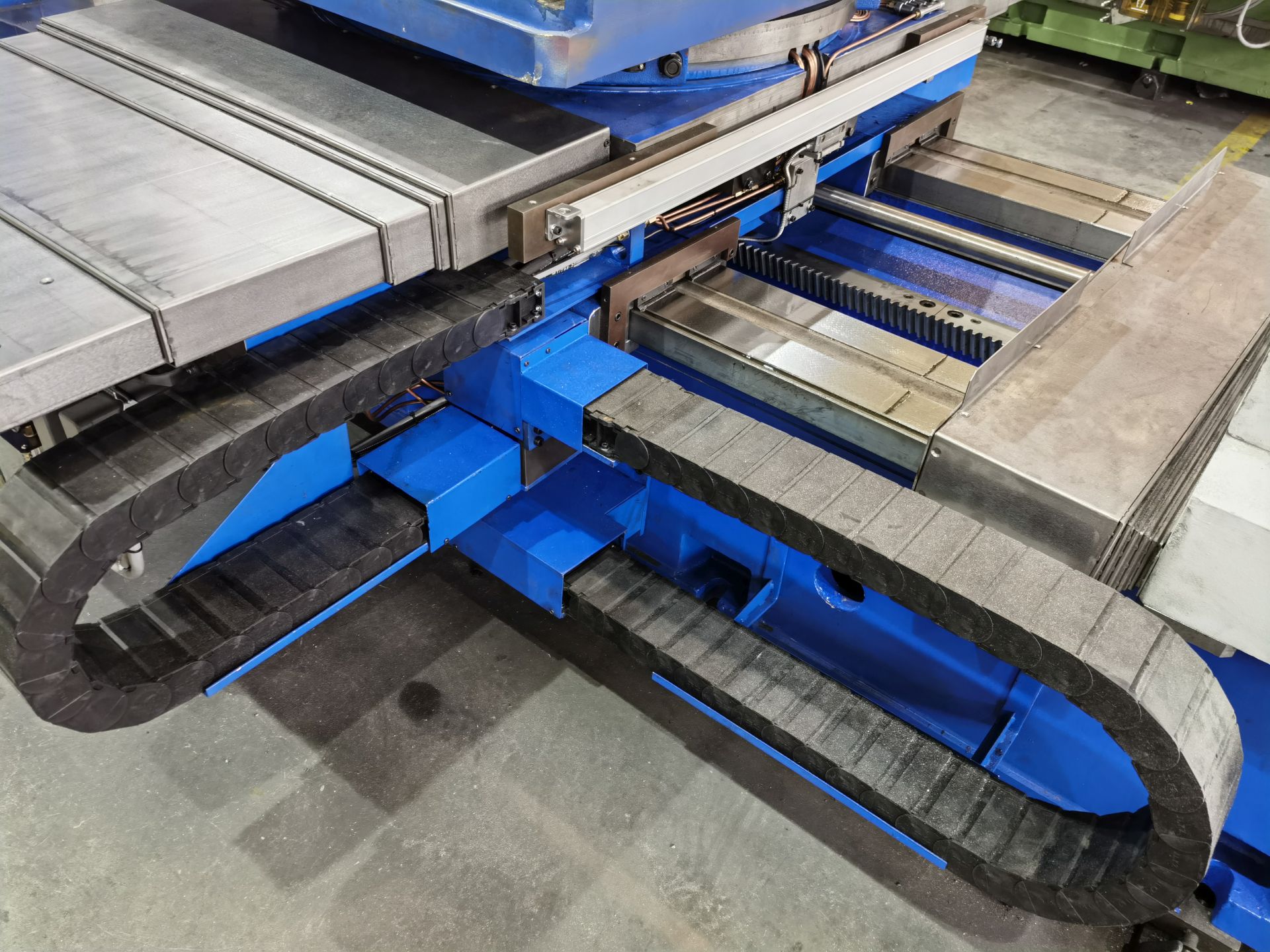
•The vertical axis is spindle box moving up and down, the traverse axis is worktable moving in cross direction and longitudinal axis is worktable moving in longitudinal direction which can be equipped with new type digital display meter with memory function. The machine features with full function and high accuracy.
Check our frequently asled question hope you get answer.
If you can't find what you're looking for
I am item content. Click edit button to change this text. Lorem ipsum dolor sit amet, consectetur adipiscing elit. Ut elit tellus, luctus nec ullamcorper mattis, pulvinar dapibus leo.
Check out our FAQ page for answers to common questions
I am item content. Click edit button to change this text. Lorem ipsum dolor sit amet, consectetur adipiscing elit. Ut elit tellus, luctus nec ullamcorper mattis, pulvinar dapibus leo.
Check out our FAQ page for answers to common questions
I am item content. Click edit button to change this text. Lorem ipsum dolor sit amet, consectetur adipiscing elit. Ut elit tellus, luctus nec ullamcorper mattis, pulvinar dapibus leo.
Still haven't found what you're looking for your questions
I am item content. Click edit button to change this text. Lorem ipsum dolor sit amet, consectetur adipiscing elit. Ut elit tellus, luctus nec ullamcorper mattis, pulvinar dapibus leo.
Check out our FAQ section for more information on how we can help
I am item content. Click edit button to change this text. Lorem ipsum dolor sit amet, consectetur adipiscing elit. Ut elit tellus, luctus nec ullamcorper mattis, pulvinar dapibus leo.
Still haven't found what you're looking for your questions
I am item content. Click edit button to change this text. Lorem ipsum dolor sit amet, consectetur adipiscing elit. Ut elit tellus, luctus nec ullamcorper mattis, pulvinar dapibus leo.
If you can't find what you're looking for
I am item content. Click edit button to change this text. Lorem ipsum dolor sit amet, consectetur adipiscing elit. Ut elit tellus, luctus nec ullamcorper mattis, pulvinar dapibus leo.
Check out our FAQ page for answers to common questions
I am item content. Click edit button to change this text. Lorem ipsum dolor sit amet, consectetur adipiscing elit. Ut elit tellus, luctus nec ullamcorper mattis, pulvinar dapibus leo.
If you can't find what you're looking for
I am item content. Click edit button to change this text. Lorem ipsum dolor sit amet, consectetur adipiscing elit. Ut elit tellus, luctus nec ullamcorper mattis, pulvinar dapibus leo.
Still haven't found what you're looking for your questions
I am item content. Click edit button to change this text. Lorem ipsum dolor sit amet, consectetur adipiscing elit. Ut elit tellus, luctus nec ullamcorper mattis, pulvinar dapibus leo.
If you can't find what you're looking for
I am item content. Click edit button to change this text. Lorem ipsum dolor sit amet, consectetur adipiscing elit. Ut elit tellus, luctus nec ullamcorper mattis, pulvinar dapibus leo.
Still haven't found what you're looking for your questions
I am item content. Click edit button to change this text. Lorem ipsum dolor sit amet, consectetur adipiscing elit. Ut elit tellus, luctus nec ullamcorper mattis, pulvinar dapibus leo.


